 was another option available to a converter which was Matrix. In the 1950’s in London, England, a Diemaker and Inventor by the name of Mr. Harry Squire founded a company called Channel that introduced to the world for the very first time, a self locating creasing matrix. This invention proved out to be a great solution for many converters. Matrix resulted in the reduction of make-ready times since they only had to be cut to length, trim the angles on the ends of the matrix, pushed onto the creases, remove the adhesive tape backer, transfer them onto the steel cutting plate and remove the plastic locator strips. Once the locator strips have been removed, use a sharp knife or chisel to chamfer the angled ends of the matrix to prevent “bruising” of the cartons. Wah la, you were ready to go. If a piece of matrix moves or becomes damaged, it is easy enough for the operator to replace individual pieces and get back up running again.
- Good for abrasive board, plastic, virgin board, corrugated board
- Recommended for long runs of 100,000 impressions or more.
- Good for abrasive board, virgin board, corrugated board
- Recommended for long runs of 100,000 impressions or more.
- Good for abrasive board, virgin board, corrugated board
- Recommended for long runs of 100,000 impressions or more.
- Easily skived, not good for plastic,
- Recommended for shorter runs less than 100,000 impressions.
- Good for all corrugated material & thicker and solid fiberboard (wider base)
- Recommended for any type of run length.
Phenolic Counterplates
Then came the 1980’s with the development and implementation of Rillma counterplates. These counterplates were cut on a CNC milling machine as a unitary plate that incorporated all the necessary crease channels for a single clone and was profiled using 160 or 170 degree Chamfer cutters to ensure that the counterplate wasn’t going to leave bruising in the corners at the ends of the creases. 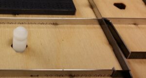 Bruising can also occur when ejection rubber is situated over the chamfered edges of the counterplate and the rubber puts vertical pressure on the substrate being die cut, over the profile. The material is malleable enough that it can be carefully carved with a chisel or knife to fine tune the counterplate on press for best results. Or if practical, the ejection rubber can be cut back to eliminate the interference. The corresponding cutting dies are fabricated with counterplate pin locating holes so that the counterplates can be positioned and transferred precisely to the press cutting plate for a perfect registration of the creasing channels to the die.
 creasing channel edges much longer than channel matrixes. This results in a crease definition that is much more sustainable, making it the better choice for dies with a higher number of clones, repeat jobs and medium to high volume jobs. Phenolic counterplates are very economical and reduce the amount of make-ready time significantly. Some additional benefits to using Phenolic Counterplates is the integration of Braille, Embossing/Debossing, Custom Cut/Crease, Custom Cut/Cutscore, Reverse Cutting or Reverse Score plates and Reverse Creasing.
- Good for abrasive board, plastic, virgin board, corrugated board
- Available up to 2.0mm (0.079”) which covers most thicknesses of solid and corrugated materials
- Recommended for long runs of 100,000 impressions or more.
- Good for abrasive board, plastic, virgin board and corrugated board
- Limited in thickness from 1 mm (0.039″), 1.15 mm (0.045″) to 1.5 mm (0.059″)
- For thicker, solid fiber or corrugated board other types are available but may require a machine modification for different cutting plate thicknesses
- Recommended for long runs of 500,000 impressions or more.

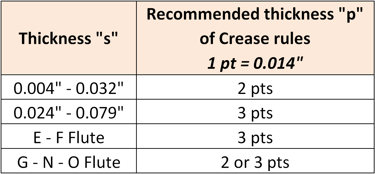

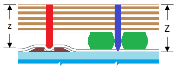


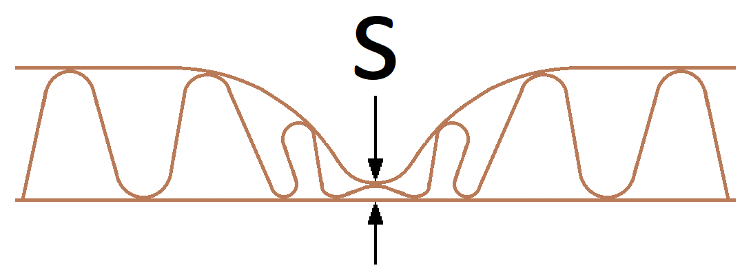


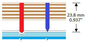
we have, relative to counterplates. Add the thickness
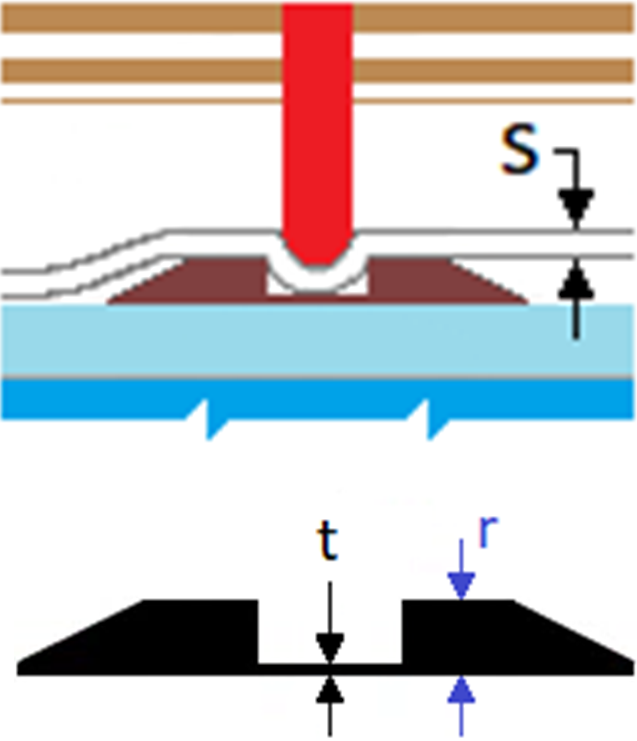
 How a crease gets “formed” in folding carton substrates
- The rubber touches the substrate which applies pressure to hold the substrate tightly against the cutting plate so that no lateral movement can take place and maintains registration between the die and the printed substrate. If matrix or phenolic counters are being used, the substrates’ fibers start to be stretched or laterally compromised over what can be viewed as a mountainess terrain, in the small world of the substrate thickness.
- The cutting & creasing rules make contact with the substrate which starts another series of reactions. The cutting edge starts to compress the substrate and the crease rule starts to pinch the stock against the two upper corners of the crease channel, referred to as the Critical Distance.
- During the continued closer of the press, the substrate gets trapped in the CD zone and starts to cause the board fibers to stretch and delaminate as the crease rule pushes the substrate into the crease channel. This is referred to as a controlled delaminating process.
- As the cutting & creasing rules get closer to the cutting plate, an immense amount of back pressure is built up which needs to be released. If the make ready of the cutting rules has been done properly with the right amount of finesse, the cutting blades will act like an axe head with the sharp edge penetrating the surface of the substrate and the angle of the wedge (54 or 42 degree bevel) causing a “burst” and separation of the substrate. This results in the cutting edge not getting damaged because it is not getting slammed against the steel cutting plate with too much force. At this instant, the crease rules have also reached their lowest vertical position and have completed the extent of a Partial Delamination of the substrate fibers. Full Delamination of the substrate fibers only occurs when the carton panels are folded 180 degrees against each other with the carton panels acting as levers.
- The last stage is when the ejection materials are pushing the substrate off of the cutting rule edges and releasing the substrate.


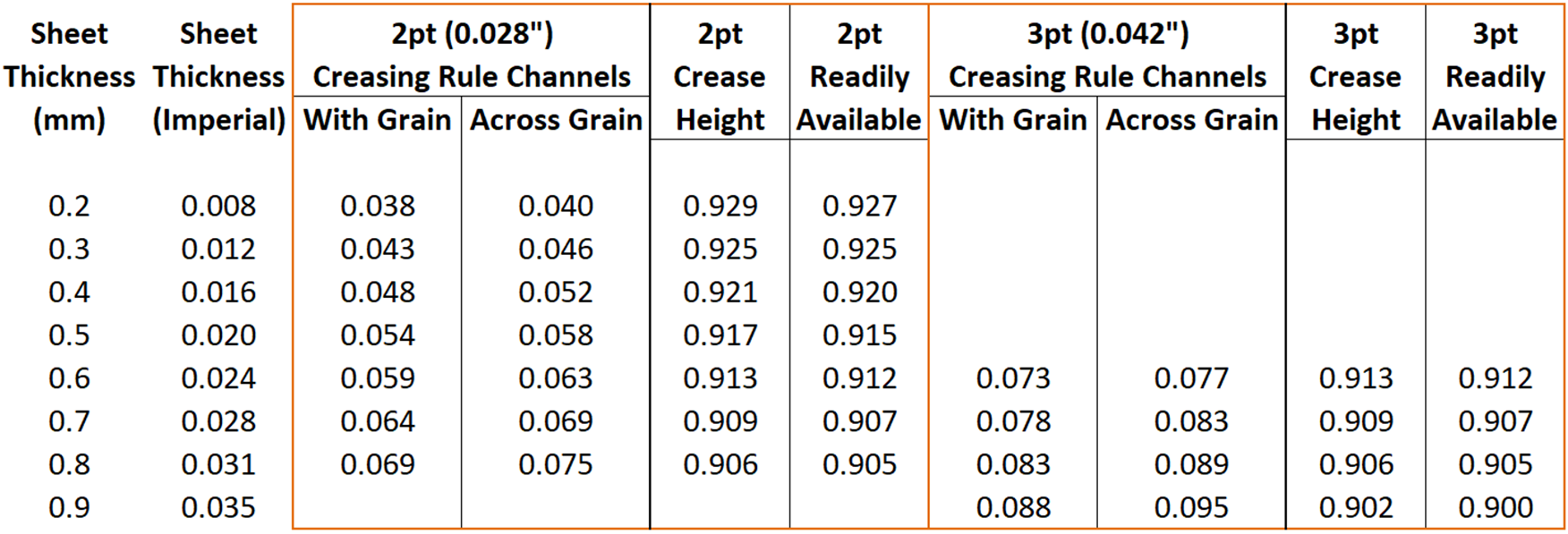
Example: WG = (0.018 x 1.3) + 0.028 = 0.051” XG = (0.018 x 1.5) + 0.028 = 0.055”
This second formula was a result of our development when performing our Crease Testing Program and is suitable for use with non-SBS & corrugated substrates. However due to the versatility of SBS, it still worked but was light on the crease bead definition.


Example: WG = (0.018 x 1.8) + 0.028 = 0.060” XG = (0.018 x 2.0) + 0.028 = 0.064”
This third scenario is a derivative of a recommended chart for Milled Steel Cutting Plates.
In Summary
Ultimately, the customer always gets the final say about what specs they want to have used. So if the customer has their own chart for Channel Depths, Widths and Crease Rule Heights, that’s what SRD will use. There is also times when the paperboard supplier may have a recommended set of specifications that would also be provided to us from the customer.
For additional supplementary information about Folding Carton Creasing, there are two informative articles in the Resource Library on the www.IADD.org website. They are as follows:
Creasing Dynamics –Anatomy of a Folding Carton Crease – by John Dickison, Bobst North America Inc.
How is a Crease Formed in Paperboard? – By Kevin Carey, Die-Cutting Works Inc.
